Understand Flow Control valve design features, specification and performance limits.
Self-study lesson plans and training record download page.
3 Tips for operating and maintaining
Always be careful that shutting some flow control valves can isolate the pipe run completely. Shutting valves may trap fluid into sealed lengths of pipe and therefore run the risk of excessively high pressures due to thermal expansion of the fluid. Another risk from closing the flow too much is that over-running loads may not be relieved enough, again causing excessive local pressures.
Hydraulic systems are generally designed to work at constant working temperatures, perhaps 40-50C. However, at startup, or even normal working when the local fluid temperature, in a remote cylinder perhaps, may be much lower, flow control valves can operate significantly differently. These differences may lead control issues or may require the system to be warmed before operating.
0.8 mm is generally accepted as the minimum size of orifice that should be used if you want to be confident of never seeing fluid contamination issues. It may be worth checking the size your adjustable orifices are set to if you keep seeing operational issues.
Remember that changing loads can have a significant effect on fluid flow rates. Watch for load changes altering your setup, or even load and temperature changes.
Understand and check how high cylinder pressures can be caused by intensification. With meter-out flow control the pressure in the annulus side of a cylinder is likely to be around twice that of the pressure supplied to the bore. The system design should never allow this to increase above the pressure rating of the cylinder and this is often why reducing valves are added into particular cylinder lines.
3-4 Design features and operating characteristics
Pressure loss
Hydraulics is a braking technology. The more pressure drop you lose in the control valve the better the level of control you have. Restrictor designs can have high-pressure losses so you must make sure there is enough supply pressure to drive the flow through the valve as well as the load.
Pressure compensated valves require a constant pressure loss to drive their control spools. This is typically around 10-20bar, which will also not be available to drive the load.
Quality of control
The orifice (or nose/seat) design is key to key to providing as flat a PD curve as possible. Non-compensated valves will always have a rising pressure drop curve but the sharper the restriction the more temperature independent it should be.
Pressure compensated valves will depend on the quality of their compensator design which is strongly influenced by the shape (detail design) of its control notches.
Adjustable flow control valves have different thread pitches such that the finer thread gives better control but less range.
The graphs show the difference between a typical restrictor and pressure compensated design. Good datasheets should also show the pressure drop for the backflow across the check valve.
Contamination resistance
From a reliability and durability point of view, the simple orifice restriction is a much more robust component than the pressure compensated spool design. For this reason, it's always better to use a non-compensated valve if the system is not dependent on a consistent speed across a range of different load conditions.
Fluid types
Flow control levels will be directly linked to fluid viscosity. Make sure to check that datasheet values are appropriate for your system fluid.
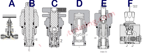
Valves A and B are simple variable restrictor valves, C is a restrictor with bypass check. Valve D is a pressure compensated cartridge valve and E the same but with a bypass check. Valve F is a higher quality industrial flow control valve which has a more stable flow characteristic against pressure and flow.
4 How to specify a flow control valve
Always understand your load before you specify any valves, but this is critical for flow control valves. Write down exactly what loads your cylinder will see across the full range of working conditions, including failure modes e.g. creep, shock, extreme temperatures, maintenance etc. Calculate the worst case local pressures under all conditions and make sure that you still have enough supply pressure to achieve the required flow through the valve.
Another key decision is whether to use meter-in or meter-out control. The primary risk with meter-in is that the actuator load tries to move the cylinder quicker than the flow controller should allow, creating negative pressure and a dangerous uncontrolled load as a result. With meter-out, the load is braked by the orifice so cannot run away. The risk now is that the bore pressure creates an intensified annulus pressure that is higher than the cylinder or valves are designed to take.
A good rule to remember this is the saying 'if in doubt, meter out'.
Another good general rule to remember is not to use an orifice below 0.8mm.
Within each basic valve type, you can find a wide range of performance and reliability differences. It is important to know how stable the flow needs to be across the full working flow, pressure and temperature range, before deciding which flow control valve to use.
4 Design Tips, techniques and potential issues
To fully understand a valve's operating characteristics you must to be able to analyse the design features within each valve. The same features appear over and again in all hydraulic valves and we've already provided a review of some key design areas in the