Understand how to specify directional control valves
Self-study lesson plans and training record download page.
3 Tips for operating and maintaining directional valves
Tip 1, 2 and 3 has to be, keep your fluid clean. The tight tolerances between the spool and bore mean that small particles of dirt can get trapped between in the gap and lock the spool in one position. Watch out for burrs or contamination in new valves, particularly grey cast iron bodied valves. The manufacturers in-house cleaning procedures may not always be perfect so checking a new valve before you put it on could save a lot of headaches later.
Never leave a valve open to the atmosphere during maintenance. If the valve internals are not fully immersed in fluid their highly machined surfaces can rust very quickly. Always keep sealed in airtight packaging during before assembly or if removed for maintenance. Plug all ports as soon as valves, pipes or hoses are removed.
Always check the full valve code including possible extension numbers at the end of the code. There are many different variants of every manufacturer's standard valves and if you do not get the exact, full code, you may finish up with a replacement valve that does not perform. Typical codes may specify, special seals, different spring forces, low energy solenoids, quiet/soft switching, special materials, low leakage etc. You'll generally have to contact the manufacturer or agent to find out what the codes mean.
Sometimes, CETOP mounted industrial valves have small orifices inserted into their ports between the mounting face. These may be changed during commissioning to achieve the desired performance although circuit drawings may not be updated to show their actual size.
Also remember that the actual onsite loads, temperatures or fluids types could also require some de-rating from manufacturer's limits.
Don't rely on a spool valve to hold pressure when the supply is turned off. The clearance between the spool and bore will always allow some leakage, which will allow pressure to vent away.
Don't try to re-machine or smooth away burrs on the spool. The original tolerances are too fine to consider manual rework. If spools show signs of scores or marking then replace with a new valve and clean your fluid.
3-4 Design features and operating characteristics
Spool manufacturing quality
The performance of a hydraulic valve depends directly on the quality of its spool and bore manufacture. In a good valve, the spool to bore diametrical clearance will only be 6-10 microns. This must remain consistent and concentric right along the length of the bore and there cannot be any burrs on edges of the bore or spool lands. Manufacturing accurate spools and bores is never easy. It is specialist work for experienced hydraulic companies with expensive machines and first-rate quality procedures.
Cleaning of the body and spools is also important for deburring and removing the loose dirt in castings. The thickness of the body can also affect potential distortions and in general, the manifold mounted style castings are less likely to suffer than cartridge style valves.
PD (Pressure Drop) vs Flow Curve
All valves have different flow passageways and fluid direction changes that will give a certain pressure drop at a particular flow. These pressure drops vary with different spool types and it's important for controlling energy efficiency and making sure you have enough pressure available at the load.
Maximum flow rate capacity
Electrically activated valves have different flow limits depending on their spool type, particularly if there is a big difference between the A and B line flows. Manufacturer datasheets generally provide clear graphs for these limits which can be significantly lower than the standard, rated values.
Valve timings
Hydraulically piloted valves tend to have higher operating forces than electrical valves so are not subject to the same flow limiting. However, they can be sensitive to the length of flow paths such that the different restrictions, fluid volumes or seals, cause some valves to operate at different speeds to others. Users need to be aware that when several valves are being used, switching timing issues can occur and issues can be seen from spikes in the return line pressure being fed back onto the valve pilot drains. These issues typically only happen with complicated manifolds and multiple interacting valves.
Contamination controls
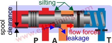
Contamination is such a critical reliability issue that if you are laying out a new circuit or trying to diagnose repeated failures, then it's worth checking the likely flow of dirt. In essence, you need to consider on which of spool lands the high pressure and low-pressure lie, and for what period of time. The leakage between the two will draw the contaminants into the spool clearance, potential collecting as silt at the end of the spool. It's now much better that, when switched under these conditions, the spool moves away from the contamination rather than trying to ride over it. It will also be advantageous to have high flow in the area where the contaminant gather.
Any area where a high-pressure difference exists across a spool, and there is no flow to take the dirt away, will be the most likely point of failure. Make sure it's not a safety critical function.
Spool leakage
Spool leakage is one of the major inefficiencies in hydraulic systems but can also be hugely beneficial for venting away any trapped in pressures. Designers must be aware of the likely total system loss when sizing pumps for large systems. Replacing spool valves with poppet valves is one way to reduce the leakage but this raises many more complicated issues that we will cover in another module.
The amount of leakage a valve produces is sometimes measurable by venting the return line into a measuring cup but difficult to capture accurately with a flow meter. The exact volume will depend directly on the fluid pressure and temperature but should not be much higher than 30cc/min on an average quality valve (VG46 fluid at 40C, 210bar).
Some spools do include an elastomeric seal to stop the leakage, although this is not possible across any control land, so is generally only included on pilot feeds. Adding a seal will limit the life to around 1 Million cycles and may add significant hysteresis to the valve.
Switching speeds and harsh operation
Switching speeds are not generally an issue unless they are too fast and there is a concern about high noise levels or harsh operation. Standard directional valves have straight-edged lands, which means they move from being shut to open, almost instantly. Solenoid or hydraulic pilot speeds with therefore make little impact.
If the operation is noisy or harsh then you can sometimes use a damped, proportional spool in a directional valve body. Proportional spools have round or triangle notches that gradually open one port into another. By controlling the switching speed with a small orifice it's possible to slow the speed at which the valve opens and therefore gradually accelerate the load, rather than hitting it with a massive hydraulic hammer. Noise reductions of up to 80% are possible with this method as is the elimination of judder.
Flow forces
Flow forces can have a significant impact on the valve's flow characteristic. Velocities inside a valve will often reach 10m/sec and with smaller local restrictions or changes in direction, there is always the potential for problems. However, in general manufacturers have designed these issues out, particularly on CETOP bodied valves, and it's only likely to be an issue when too small cartridge valve has been used in a custom manifold, at which point the flow quality probably does not matter.
4 How to specify directional valves
Select your directional valve based on your application. Mostly it's clear whether it is industrial or mobile etc. but if not, there is probably some similar equipment you can replicate. The main factors will probably be the environment, duty, maintainability, weight or cost. If you are building one machine and you want it to work 'first time' then it's probably a CETOP platen mounted valve, but if you have time for some development then you can probably get a smaller and cheaper design using cartridge technology.
If you are uncertain about what type of directional valve would be best for your conditions then write down all of your environmental conditions and send them to the manufacturer or his agent. I actually recommend writing a clear equipment specification for every project. We will provide a sample specification in our project planning section.
Check working pressure limits, including those from cylinder intensification, if appropriate. Pay particular attention to the maximum tank line pressure. Some valves are restricted to very low values whereas some application put high pressures onto return lines that the manufacturer may only have intended for use as a low-pressure tank return lines.
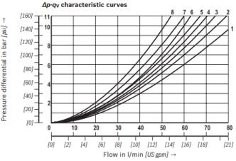
Look at the component's datasheet to select a valve with the necessary flow rate. Make sure you know how much load your actuator needs under the worse conditions and what pressure loss you will get from the rest of the system. Then select a valve with a low enough pressure drop for your supply pressure. Valve flow ratings will be different for each spool and probably lower than the headline figure quoted for that particular valve type. The first graph shows a number of different PD vs Flow curves for different versions of the same valve.
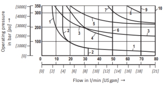
The second graph shows the performance limits for different versions of the same valve. With high-pressure drops and more flow through one side of the valve than the other, these performance limits can be much lower than the quoted maximum. Adding a small orifice underneath a platen mounted valve is a possible solution to reduce the maximum flow.
Flow capacity will also vary with different fluids and operating temperatures, in particular, cold start conditions. If solenoid temperatures get high then their performance will be reduced and maximum flow rates will be affected.
Select an appropriate spool centre position. Consider what you want to happen to the load in the standby condition. Do you want its movement to be restricted with an A, B closed spool or free to move with an A, B to Tank spool etc.. Next, consider the switching conditions. Some datasheets show the spool crossover arrangement as it switches between each of its three main working positions. This can be important if you don't want to lose control of your load as you switch. Also if you have a fixed displacement pump but the valve ports close as it switches, then you'll probably get excessive pressure peaks as it switches.
Directional valves will generally work with most types of fluid (mineral oils, biodegradable, fire resistant) but always check datasheets for recommended derating levels as well as seal compatibility.
Wet pin solenoids are generally preferred as these coils are removable and have fewer exposed parts that might corrode and fail. The choice of DC, AC or EXE solenoids etc. is generally dependent on the location of the plant so there is usually no opportunity to consider options for change. Many different connector options available.
Generally, there are several different types of hand emergency, manual override systems available, but like other features, the manufacturers don't always put all of them in their datasheets.
Always consider the crossover conditions, e.g. closed or open flow. This can be a common error with 4 way 2 position valves which need to have open centres for fixed displacement and closed centres for variable displacement pumps.
If you are using detented valves then check you won't need return line checks to stop backpressure peaks causing unintended spool movements.
Position monitoring is sometimes available to let users or control systems know what position the valves is currently in.
4 Design tips, techniques and potential issues
Remember you will always get leakage between the port lands on a spool valve. Some valves more than others. Make sure you cleanly vent unwanted trapped in pressure away. Also be careful that your load does not move due to the leakage when the system is turned off. Although be thankful that spool leakage removes the risk of trapped in pressure exceeding the maximum equipment pressure due to thermal changes. You get a lot less trouble with spool valves than poppet valves.
Be careful that the valve does not need a low tank return line pressure on one port. Pressurising the end caps on some valves is not permitted and risks blowing the ends of the valve off.
Make sure you have a stable reference pressure for switching, this is often the return line pressure which is susceptible to pressure spikes from the main return flow. Because pilot pressure is small compared to the main system pressure, normal changes in the system pressure can be reflected back onto the pilot lines making them unstable and causing the valves to inadvertently switch when not required, or not switch when they are required to.
Harsh operation and noise can be an issue with directional valves. Although you can use flow control valves to reduce the speed, you cannot slow the actuator acceleration with standard directional valves. It's worth calculating the system natural frequency to investigate if proportional valves (see Design Strategies) are required but there are 'soft start' valves switch more slowly and will gradually accelerate the load, therefore working a lot more smoothly and quietly.