Understand servo and proportional valve design features, specification and performance limits.
Self-study lesson plans and training record download page.
3 Tips for operating and maintaining
Proportional valve require good pressure drop across them to provide the energy need to control the load, these are typically 30% of the load pressure. Proportional valves need this extra pressure drop (p.d.) to control the flow. It's more common for servo and proportional valves to give problems due to being oversized than undersized. This means they don't have enough of a restriction or throttling effect to maintain good control. Don't be afraid to use a smaller valve if there is sufficient pressure drop available although always ask the valve supplier first.
A proportional valve creep speed should be approximately 1/6 of the full speed.
High-performance servo valves may require a 70 bar p.d. to control the load. These are also likely to be operating in closed loop control. This is when the actual position of the load is fed back into the electronic control systems so that it can be compared against the desired position for where it should be. The difference between the two is calculated an appropriate drive signal is sent back to move the valve. Closed loop control systems create complicated machines. Someone should have calculated their performance and sized the components correctly using some form of computer simulation. Adjusting the PID (proportional, integral, differential) control gains within the feedback loop should only be undertaken by a suitably training commissioning engineer.
In industrial design, it's common to build in high p.d. losses to make sure of achieving good control. In mobile design any inefficiency will result in extra fuel consumption so additional development work is often undertaken to find an acceptable level of control with minimum pressure loss. What this means for maintenance is that on industrial systems there may some margin for adjusting the control to give better performance or efficiency. However, on mobile equipment, you may only have a narrow margin to set the valves in order to have confidence they will perform across the full range of operating conditions.
Consider the valve and control system as one unit. Modern PLCs have hydraulic valve controls built in and hydraulic manufacturers have their own control cards or devices to ensure good control in a relatively simple way.
Keep your fluid clean. The finer the control the more a single piece of contaminant will affect its operation. You should run around 1-2 points cleaner on the ISO scale for proportional and 2-3 for servo control, probably 5 or 3-micron filters with beta 200 ratings. It can sometimes be very difficult to predict exactly how effective the filtration system will be at the design stage. We recommend using inline contamination meters to check the actual level of contamination during normal operation, if the design does not maintain a suitable level of cleanliness then try introducing a cleaning procedure where fluid is circulated around the system purely so it has the opportunity to repeatedly pass through the filters to clean the fluid, without doing any actual work, which might make it dirty.
Expect more wear on the valve's control lands in a high performance or arduous application e.g. high flows and temperatures across the lands. Expect to see more effects from wear on the control lands with high precision valves because their spools have tighter tolerances that are therefore more quickly eroded due to contamination and high duty. Expect to change them more often than lower performance valves.
Look after your fluid well, its life may be reduced due to the higher valve pressure drops and high local fluid temperatures. The extra shear forces within the fluid, due to the high load braking forces, put extra strain on the fluid, which can result in changes to the fluid's properties.
Valves without internal electronics tend to be more reliable in arduous conditions that with electronics. In steel mills, for example, they often prefer to use mechanical feedback, flapper style servo valves than valves with equivalent performance but using internal electronics.
3-4 Design features and operating characteristics
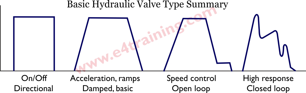
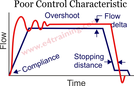
This diagram summarises the basic valve control groups. Curve 1 shows the basic open/close operation of a directional valve. Curve 2 could be a directional valve with a proportional valve spool and damped opening or a simple proportional valve. Curve 3 is a typical automated industrial machine where the cylinder needs to have an accurately repeatable cycle and always stop in the same position. Curve 4 represents a closed loop servo valve that can follow most highly dynamic input signals.
Proportional or Servo? Originally there were clear differences between the design and performance of proportional and servo valves. Servo valves were always the Moog style valve with an overhead torque motor rather than solenoids, and mechanical feedback arm linked to the valve's flapper nozzles. Modern, high-performance proportional valves may still look more like directional valves but their improved design with internal closed loop electronics does mean they can achieve a similar performance to a servo valve and may therefore be named as such.
Spool Notches
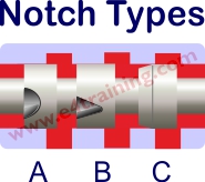 Circular notches provide a gradual opening but it is not linear with respect to spool displacement. They are primarily used in lower quality or manual valves because they are relatively cheap to produce with a single cutting tool. Triangulated notches provide a more linear opening characteristic but require more machining work to make them. The third example shows a chamfered notch as used on a high-performance proportional valves to give the most linear performance and faster opening speeds.
Overlap Tolerances
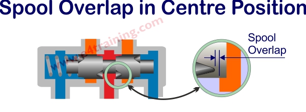 Spool overlap is defined as the percentage of spool stroke that the valve is closed in the centre condition. An underlap, or negative overlap would allow leakage in the centre position. Accurately machining the controlled overlap of both spool and body is very difficult. For cast body valves this may simply be against the internal cast galley ways which will have limited dimensional tolerancing. Machining the lands inside the valve bodies will improve tolerances but still has limitations. High-performance valves have machined inserts to allow the tightest tolerances to be controlled.
Maintaining accurate overlap tolerances is important for avoiding the jump in mid position as the valve switches from supplying flow to port A or B. Different types of control will require different levels of overlap, for example, pressure control is often better with negative overlap valves. Always seek the manufacturer's advice for high performance or closed loop control applications as they can accurately predict the expected performance using simulation.
Valve Natural Frequency
The dynamic performance of a valve is specified by its natural frequency. This defines how quickly it can move from one position to another position and is defined by the frequency at which the valve lags by 90 degrees in the phase response curve. Manufacturers do not generally quote the figures for lower performance valves in their datasheets as this is normally only relevant for more dynamic, closed-loop applications.
Minimum Acceleration Time
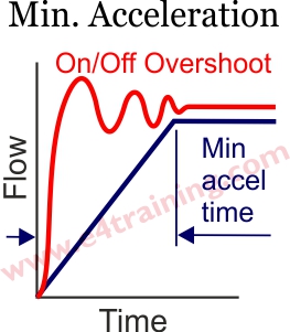 To avoid any judder or harshness as the valves are switched you must ensure that the cylinder is not accelerated too quickly. The minimum acceleration time is calculated from the system natural frequency and is known as the minimum acceleration time.

Closed Loop Control
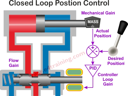 To achieve the fastest response and most accurate levels of position, flow or pressure control, it's common to drive high performance proportional valves and servo valves in closed loop control. This requires measuring the actual position of the load and comparing this value with the desired value for where it should be. The difference, or error signal, is then amplified by a mathematical gain value, often including Proportional, Integral and Differential (PID) elements, which is used to drive the hydraulic valve to its new position.
Closed loop control requires a full understanding of the system natural frequencies and loop gains and should only be attempted by people with the relevant experience.
3-4 How to specify a proportional valve
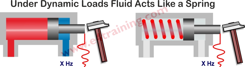
Although hydraulic fluid is often considered to be incompressible, it is, in fact, compressible, and this is important when designing proportional control systems. The diagram shows how hydraulic fluid acts like a spring when subject to a shock input such as being hit with a hammer or the instantaneous opening of a hydraulic valve.
The system stiffness is defined by its natural frequency and you should always start your proportional valve specification by calculating this for your own overall mechanical-hydraulic system. You can use our valve/cylinder design guide for this (not appropriate for all situations) or simply hit your system with a big hammer and measure the frequency at which it oscillates.
Typical values might be:
Less 3 Hz (4 Hz with pressure compensator) don't try to control anything below this unless you really understand adaptive control.
3-10Hz e.g. manual control of excavators or ramped opening and speed control of industrial plant, to stop it juddering etc.
10-20Hz good industrial open-loop control and closed loop mobile applications.
20-80Hz industrial closed-loop control with motion control simulators and machine tools at the higher values.
Above 80Hz are the high-performance systems reaching 400Hz and above for good quality tensile test equipment.
Select a valve with three times the natural frequency of the system to ensure the valve maintains control with no interaction. The overall equipment natural frequency is based on a combination of the valve and system natural frequencies.
Make sure you have sufficient pressure available for the valve to adequately brake and control the load. A common error is to oversize a proportional valve so that you have plenty of pressure drop available for the load, but control will be poor. You should try to use a smaller valve that has a higher pressure loss and therefore gives better control.
Consider the direction of your load and select the spool cut to suit. For example, if you are raising and lowering a load you might want to use a 2:1 ratio spool. This has a bigger opening on the unloaded side of the cylinder than the loaded side. This means you have good control of the load when you lower it but don't waste energy on the unloaded side when you raise it. Therefore better efficiency with no reduction in safety or control.
You may also want to specify a particular spool underlap or overlap to suit the type of control system you will be using but again this is normally only of concern for high-performance machines and if you are working at this level then you should already be discussing performance simulations with your valve suppliers.
4 Design Tips, techniques and potential issues
Unless your system is very simple or you've made them lots of times before, then it's always worth running a proper dynamic simulation as static calculations of proportional control are not very effective.
Make sure your system has as high a natural frequency as possible. This will be helped by large area cylinders and short, small bore pipes. It will be made worse by using pressure compensators, single lines control valves or pumps controls on the pressure line only. Adding grease or other lubricants to the mechanical drive system may also significantly affect the design. Always remember that the reflected mass on the system is based on the square of the radius arm.
Check your natural frequency by simply hitting the load with something heavy and then measuring the frequency of the pressure oscillations.
Proportional valve pressure drop should be approximately 30% of supply pressure.
Servo valve pressure drop approximately 70 bar.
Proportional valve full speed to creep speed ratio around 6:1.
Typical maximum cylinder speeds are:
100 mm/sec directional valve without cushions.
200 mm/sec directional valve with cushions.
500 mm/sec max. for standard cylinders.
1000 mm/sec servo cylinders.