4 way 3 position, directional valve performance data
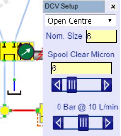
Left click on the valve model to open its settings.
Select the spool centre condition from the drop-down list box. The symbol will show which one is being used.
Enter the nominal bore size in the second edit box, use 6 for and CETOP 3 (NG6). This will affect the pressure drop through the valve at higher flows.
Set the spool clearance in micron. This determines the amount of leakage through the valve across any land that is closed. All spool valves will have leakage although poppet valves will be virtually zero and have not been checked yet.
Adjust the flow slide bar to see a typical pressure drops across the valve. Usually, valve datasheets have typical flow vs pressure drop curves for each spool so you can adjust the nominal size to give the most appropriate curve if the size is not specified.
There are no valve dynamics included.
3 way and 4 way 2 position, directional valves
You can use a 4 way valve and simply leave ports unconnected and the simulation will assume they are blanked. Any fluid leaking into the PC does not create a safety issue in this simulation.
2 way 2 position valves
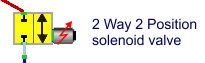
The two position two way valve uses the same setup options as the 4 way valve but is only available in 'normally open' and 'normally shut' versions.
Check valves
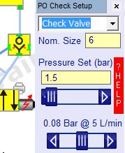
The check valve model can be used with or without pilot operation. Note that the pilot lines only transmit pressure signals, not flow.
Left click on the check valve icon to open the setup menu where you can set the nominal size and spring pressure. The bottom slider gives a guide to the flow pressure drop for the size of valve selected.