Self-study lesson plans and training record download page.
Variable Displacement Pump Controllers
This section will review the different types of pump controllers. We discuss how they work and what they are used for. Please note our circuit examples show the basic approach but do not show details of all of the orifices and feeds that will be in the different manufacturer's pumps.
An important factor with pump controllers is the stability of the pilot lines. For example, where the pressure controller drains vent to, this may just be the pump casing but then you must be confident that the flow peaks, that occur as the controllers change, do not create pressure peaks in the drain lines or pump casing. This can further complicated by the length of the drain or load sensing lines etc. Controller flow rates may not be published in the manufacturer's datasheets and on some models can be higher than you'd think. Watching to see if the hoses 'kick' is one way of identifying symptoms although measuring this is the only way to find the pressure peaks within your system.
A significant difference between the mobile and industrial pump controllers is their pressure setting differentials. Industrial pumps are typically sold to a large number of different equipment builders and often for 'one-off', custom machines. To ensure reliable operation on every system and with all types of pilot control line lengths, the standard controller differential tends to be set quite high, e.g. 30 bar. However, pressure loss, is an energy loss, is money lost, so reducing this would be better. On mobile machines, their performance is measured by fuel consumption so power loss is critical. To ensure the best fuel consumption OEMs (Original Equipment Manufacturers) will spend many development hours checking and testing their systems to ensure they can run with lower pressures, perhaps as low as 15 bar. Industrial suppliers may also optimise their controller pressure when producing production machines, but there will always be the risk of control issues due to equipment interactions if operating differentials are reduced.
Two position switching control
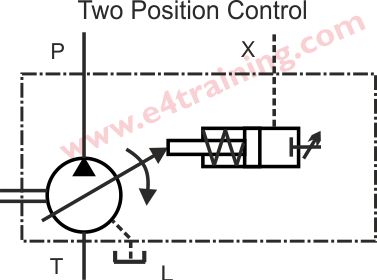
This is a simple control that has two flow settings.
This would be used in a range of different machines where they only require one fixed flow, perhaps a machine tool switching on and off. The single fixed flow is set by the adjuster, otherwise, the flow will be zero when pressure is applied to the X port. A spring returns the swash plate position to zero when there is no pressure applied.
Pressure compensated control
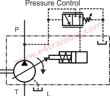
A pressure compensated pump will maintain the system at a constant pressure, whatever flow is required by the system. That is provided the flow demand of the system is below the maximum capability of the pump.
Constant pressure controlled pumps are widely used throughout the majority of industrial application. It's also common to have a bank of pumps all supplying the same system, although balancing features are required above a certain number of pumps, as recommended by the manufacturer.
The pressure control valve works because the proportional control spool in the control is pushed against the adjustable spring. Once the system pressure reaches the spring setting the controller will move smoothly across and use the supply pressure to reduce the swash plate setting and therefore the flow from the pump.
Remote pressure pump control
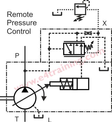
A remote pressure control is used when the operator is located some distance from the pump but still needs to control the pressure locally. The small, pilot pressure control valve can be situated at the operator's workstation allowing him full control of his equipment.
Remote pressure control is likely to be used on test equipment or machine tools etc.
The controller example shown, still retains the pressure compensation feature as a backup, maximum pressure device. The remote pressure control valve is attached to the X port and de-pressurises the back of the spool.
Pump flow controller
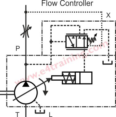
Flow controllers allow the pump to provide a constant flow depending on the setting of the flow control valve. It's common to include the pressure limiting valve in the controller as well as the flow control spool, although we have not shown this in our example.
Flow controllers may be used on test rigs or machines that require variable speed.
Although we are now controlling flow, the controller is receiving this signal as a pressure difference across the variable orifice in the supply line. The pressure difference is sensed on either side of the spool so as the flow increases the pressure difference moves the spool across to adjust the swash plate and maintain the required flow.
Pump electronic control
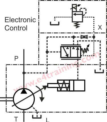
An electronic control will allow real flexibility of how and where you control the pump pressure. The input for the electronic control valve may simply come from a remote manual control knob or may be linked to a full machine control system.
Electronic controllers may be used within a wide range of automated machine control processes.
The electronic controller works in a very similar way to the remote pressure control system, except now the pilot pressure control valve is integrated into the pump and only its signal is remote.
Pump power control
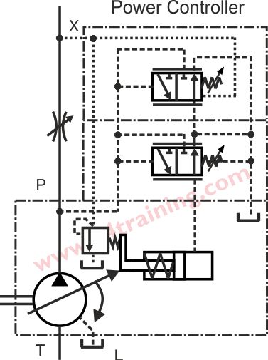
The power controller limits the maximum power the pump can supply. This may be used on mobile or industrial systems where the maximum capability of the pump is greater than the installed power from the engine or electric motor.
An example of where a power controller is used would be an excavator that requires the maximum pressure for some actuators and maximum flow for others. If the operator tries to use too many actuators at once the power control will restrict the power from the pump rather than stall the engine.
The power controller includes both a pressure and flow control valve. The pressure restrictor is actuated directly from the swashplate angle, therefore, restricting the maximum pressure available at full swash.
Load sensing pump controller
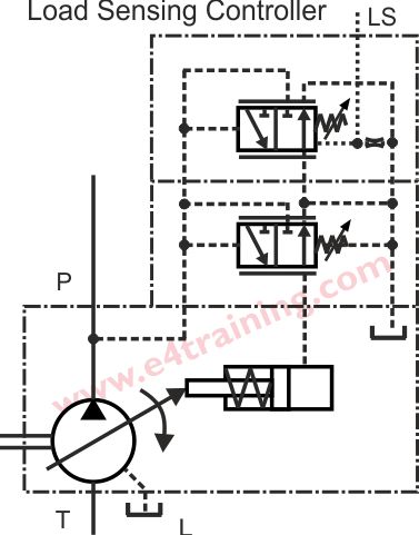
Load sensing is when a required pressure signal is sent back to the pump by individual consumer control valves to indicate how much pressure they require to move their loads. Load sensing can save a significant amount of energy because if a load only need 100 bar at 50L/min then that's all the pump will provide. A pressure compensated pump would always produce the maximum pressure available and if this was 315 bar then over two-thirds of the energy would be wasted as unwanted heat.
Load sensing pumps are common on many mobile machines and boat systems. They will only work if the directional control valves used include a load sensing feedback signal. LS boost valves may also be required if the LS signal travels back via long feed pipes with significant pressure losses.
The pump load sensing controller work in a similar way to the remote pressure control valve whereby the LS pressure is sent back to one side of the control spool, moving it across to increase the pump flow when the pressure drops. However, the LS controller takes its pilot flow from the directional control valve's LS signal rather than the pump's supply, as in the case of the remote pressure controller.