Self-study lesson plans and training record download page.
Learn to operate a skid-steer excavator
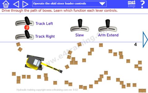
Mobile excavators usually have a range of different systems controlled by hydraulic actuators. In our example we look at:
Wheel drive motor
Forward and reverse drive and the steering system are controlled by separate left and right wheel drive motors. With only the left drive motor turning forward the tracked vehicle will skid to the right. With only the right motor driving forward it will turn left but with the right motor driving backwards, it will turn right.
Moving both drive motors forward at the same time the vehicle will travel in a straight line. But if the left motor is turning at a slower speed than the right motor, the vehicle will turn slightly left.
Cab slew
The driver's cab can be rotated through 360 degrees by a hydraulic motor and geared slewing ring. In our example, the cab is controlled by an ON/OFF hydraulic control which means it turns at either full speed or is stopped. In the drive and boom extend controls the speed of movement is proportional to the position of the handle. In practice, machines may have either proportional or directional controls on some or all of the functions, depending on their application, quality, and price etc.
Boom (arm) extend and retract
The boom is extended and retracted using a hydraulic cylinder. The arm lift and bucket tilt and grab are also likely to be moved by hydraulic cylinders.
Learn how three hydraulic functions work
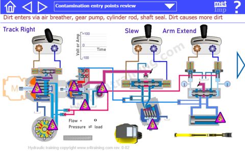
Screen 2 explains how the main functions of a hydraulic skid-steer excavator are likely to work and the types of components they use.
System 1 is a closed circuit, hydrostatic, drive system
A ramped electrical signal is generated proportional to the joystick lever angle.
The electrical signal operates a proportional pressure control which gradually changes the pressure on the swashplate piston.
The swashplate piston moves against a spring to change the angle of the pump swashplate.
The displacement of the pump changes with swashplate angle. The higher the angle the more the outlet flow.
Hydrostatic drive pumps can operate with the swash going over-center, thus providing the flow in forward and reverse directions.
The Low-speed high-torque piston motor has fixed displacement, therefore turning the wheels at a speed relative to the flow.
The motor can work in both directions
There are no valves within the closed pump and motor circuit, this provides an efficient drive system with few energy losses, and gives the system its name 'closed circuit'.
System 2 is a load sensing, open circuit slew and lift system
The second piston pump provides flow when the slew or lift systems are operated.
The load demand from either system is fed back to the pump as a pressure signal via the shuttle valves. The highest load pressure signal reaches the pump control valves.
The load sensed by the pump control applies a proportional pressure signal to the swashplate piston.
The swashplate piston moves against a spring to change the swashplate angle. Importantly, a small pressure loss is always required power this function, even while at standby.
The swashplate controls the pump displacement and therefore pump output flow.
The pump output pressure will be typically 18 bar (260 psi) higher than the feedback signal meaning there is a small power loss used as the energy to control the pump etc.
System 3 is a fixed displacement gear pump for makeup and pilot pressures.
The third pump provides a small constant flow into the pilot system
The arm extend/retract system uses this to pressure to supply the pilot pressure reducing valves.
All unused flow passes into the low-pressure hydrostatic circuit line to make up for the flow lost through the pump and motor leakage, plus provide some excess flow for cooling.
System 4 is a slew system with closed-center, directional valve
An on/off, positive and negative electrical signal is activated as the joystick lever is moved.
The electrical signal switches the position of the directional valve via direct-acting electrical solenoids.
The directional valve is either fully open in one direction or the other, or restricting all ports in the center, inactivated position.
The fixed displacement, bent axis, piston pump rotates in either direction, at a speed dependent on the flow rate.
The flow rate is controlled by the small orifice restriction above the directional valve.
The main energy loss in this circuit is only the pressure drop across the orifice.
System 5 is a boom lift system with proportional flow control valve and cylinder
A ramped electrical signal is generated proportional to the joystick lever position.
The electrical signal operates either of two proportional pressure reducing valves which give an output pressure proportional to the electrical input signal.
Applying pressure to either side of the spool valve moves the spool an amount proportional to the pressure signal.
As the proportional valve spool moves it opens and closes an orifice at each port.
The changing orifice size restricts the flow, or increases it, up to that required to move the cylinder at the desired speed.
The cylinder actuator moves in either direction depending on whether the flow enters the annulus or bore side.
Understand the hydrostatic drive system closed circuit schematic
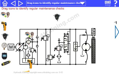
Hydraulic circuits are designed and explained using a standardized library of symbols to ISO1219. Each symbol represents a different component and should explain the important features within that product. Further information on the range of symbols available can be found here.
The following table is a summary of the parts shown in our hydrostatic drive circuit shown in screen 3.
| Component | Description |
|---|---|
| Piston pump | Main supply piston pump - Provides flow in both directions proportional to elec. signal |
| LSHT Motor | Drive motor - Converts fluid power to the bi-directional rotational wheel drive |
| Gear pump | Charge pump - Supplies pilot pressure to control valves and makeups fluid lost by leakage |
| Flexible Hoses | Hydraulic hose allows for movement between the wheel-motor and solid pipework |
| Fluid filter | Filter cleans the hydraulic fluid before enters the closed-circuit |
| Air breather | Filters the air to restricts dirt entering the reservoir as the volume changes |
| Relief valve | Charge relief valve maintains pressure by controlling flow into the return side of closed circuit |
| Check valves | Check valves allow flow into low-pressure line but prevent flow from high-pressure line |
| Relief valve | Crossline relief valve ensure overrun loads do not exceed maximum circuit limits |
| Relief valve | Crossline relief valve ensure overrun loads do not exceed maximum circuit limits |
| Directional valve | Flushing valve recirculates the excess charge pump flow down the return line and back to the reservoir to cool and filter |
| Shuttle valve | Brake release shuttle directs the highest pressure from the drive side of the circuit to release the parking brake |
| Relief valve | Relief valve maintains a positive pressure in the closed-circuit return line |
| Cooler | Cooler, heat exchanger reduces the fluid temperature before it returns to the reservoir |
| Fluid reservoir | Reservoir stores and conditions the hydraulic fluid keeping it clean and free of air bubbles |