Self-study lesson plans and training record download page.
Basic closed circuit drive system
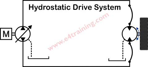
This image shows the basic, closed circuit, hydrostatic drive system. On the left, we have a pump driven by an engine. The pump can swash over-centre allowing the flow to be supplied out of either port e.g. in a clockwise or anticlockwise direction around the circuit. The motor on the right side of the circuit (could also be a cylinder) is able to rotate in a clockwise or anticlockwise direction, depending on the flow it receives.
The beauty of this simple design is that there are no valves or other control components that require pressure drop or use energy to operate. By removing the normal hydraulic control losses the system is much more efficient.
This type of hydraulic system is often called a closed circuit (NOT closed loop) because the return lines are not open to atmosphere via the hydraulic reservoir head.
Charge pump to make up leakage losses
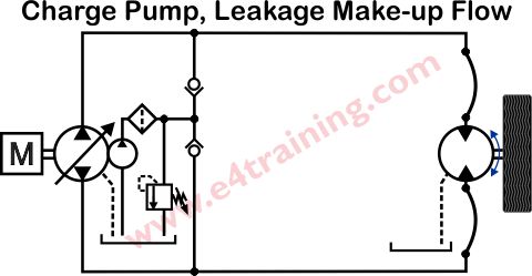
Piston pumps and motors always require a small case leakage flow to lubricate the bearings and remove the temperature fluid. A small charge pump is therefore required to make up this lost fluid and ensure there is always a positive pressure at the main pump suction. A relief valve is used to control the flow and pressure entering the circuit and check valves ensure the fluid is always passed into the low-pressure part of the circuit. The charge pump is also often used to filter the fluid before it reaches the main circuit.
Closed circuit overrun relief valves
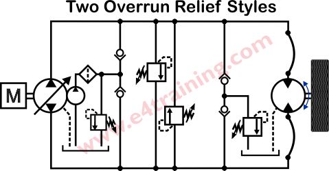
Hydrostatic transmissions often perform very quickly with big loads and high accelerations and decelerations. When braking a heavy vehicle, for example, the weight of the vehicle will be taken through the hydraulic motor, potentially generating huge pressures inside the closed hydraulic circuit. Relief valves are used to vent any excess pressures from the high to the low side of the circuit.
This image shows examples of two different styles of overrun relief valve in one circuit. In the middle, we have two cross-line relief valves venting directly from one side to the other. On the right, just left of the motor, we have a single relief valve venting the high pressure via a shuttle valve arrangement, to tank. Either may be used depending on which best suits the system requirements.
Flushing valve with cooler
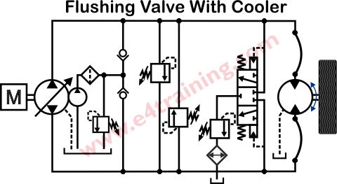
This image shows the addition of a flushing or hot flush valve. The valve spool is activated from the high-pressure side of the circuit but then opens the low-pressure side of the circuit to tank. The relief valve, shown after the 3 way, 3 position spool, now sets the pressure in the low-pressure side of the circuit. This means that all of the charge flow, less any leakage, is passed through the closed circuit and therefore helps to keep the system cool. This flow can also be fed back into the motor casing to provide a more effective flushing flow to cool the motors.
Brake release valve
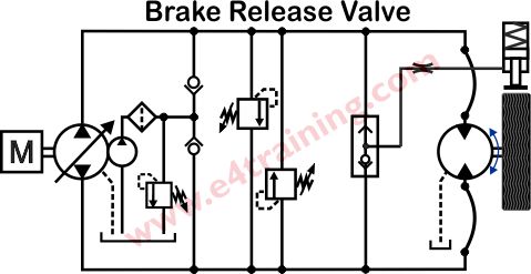
A potential safety hazard of closed-circuit designs is that if one of the hoses breaks, hydraulic pressure will be lost from the whole circuit and the drive motor will be allowed to rotate freely. Potentially causing a vehicle to run away, out of control, or fail to stop when required. To overcome this issue the wheel motors are often supplied with integral, mechanical brakes. The brake pads are spring loaded to be continuously on until the system supplies a high pressure to release them. With this design, if the system pressure fails, the brake will fail as well.