Different types of proportional control valves explained
In this section, we will look at a range of different control system examples to understand why each type of control is needed and which valve features are required to achieve them.
Manual flow control

Many mobile  machines require the operator to move a handle to control the position of a heavy load. Basic proportional valves regulate the flow rate depending on how far the lever is moved. A directional valve would be either open or shut and would not, therefore, provide enough sensitivity in the control. If only one flow rate was ever required then a flow control valve would be used. But when the flow rate needs to change then an adjustable flow control or proportional valve will need to be used.
Features required
A notched spool is all that is required for manual proportional control. The notch quality is not critical because the human operating the handle will be very skilled at adjusting the amount of movement required.
Factors to consider
Protection against contamination is also not so important because human hands will provide a far higher force to clear particles than a solenoid can.
The pressure drop across the spool with vary with load and therefore so will the flow rate. The operator will need to watch and adjust the handle position based on the speed the load is moving.
Experiment to find out more
Remote manual flow control
Some mobile machines locate the control levers away from the control valve itself. The handle that the operator will move will generate either an electrical or fluid pressure signal that will be sent back to the main control valve. It's likely that both electrical and pressure feeds will eventually supply a small pilot pressure signal (via a proportional pressure reducing valve with the electrical signal) onto each end of the main control valve spool. This is known as a pilot pressure control system and the performance is very similar to the manual flow control system.
Features required
Either a pilot pressure supply system or an electrical control system with proportional control levers, analog or digital control module, and proportional solenoids that may work directly on the end of the main spool or drive proportional pressure reducing valves that feed the end of the spool.
Factors to consider
Pilot pressure signals are generally quite low when compared to the main load pressures. This means they can be sensitive to oscillations in the main supply or tank return lines. Pressure fluctuations, particularly in the return line, are likely to be felt by the pilot control pressures as well.
Experiment to find out more
Electrical flow control
Many industrial  machines rely on electrical control systems to regulate the amount of flow supplied by a valve. Automated machines require the same speed i.e. flow rate, over and over again. This means providing the same flow rate each time the valve is opened by a set amount. And this is very difficult to achieve. As we mentioned with manual control, the human constantly adjusts the handle position to find the speed they require. With automatic control, the spool must be positioned incredibly accurately by the solenoid force and the flow rate through the orifice area created, which will vary depending on the pressure difference and fluid viscosity. This means that any changes in the supply voltages, temperatures, load or supply pressures, valve wear, contamination, or even ambient conditions, etc. will affect the actual flow rate achieved. In fact, these influences are often so big that we assume an accurate speed will not be possible and commonly use a lower, creep speed, if cylinders need to be positioned accurately.
Features required
The most common types of proportional solenoid will apply a force onto the end of the spool roughly proportional to the PWM (pulse width modulated) current supplied. This force will move the spool against the spring on the other side of the spool. Alternately it is likely that proportional pressure reducing valves are used to apply a small pressure onto one end of the spool to move it against the opposing spring.
This to With basic proportional control features, it is not possible to accurately control the speed or stopping position of a cylinder so other considerations will be required based on each machine's operating requirements.
Factors to consider
We will consider the range of options for improving the accuracy of proportional control in the following paragraphs.
Experiment to find out more
Experiment with load pressures and limit switch position here
Proportional flow and pressure control valve
It could perhaps be argued that most pressure and flow control valves are actually manually operated proportional valves, but they are never known as this. However, when the valves are fitted with a proportional control solenoid so that they can be continuously adjusted remotely, they are generally known as proportional flow and pressure control valves.
Forces acting on proportional systems
If a proportional valve is used it's likely this is because the load is relatively big or require fast movement. So it is important to understand all of the loads that may be acting on the system.
Static loads
What is the total moved mass acting on the system e.g. load plus framework? How does the load change as the cylinder moves and does it go overcentre i.e. pushing and pulling the cylinder?
Dynamic loads
Accelerating and decelerating a load takes more force than simply supporting it. Accelerating the mass of fluid in the pipework may also be significant in higher performance systems.
Force required = Mass x Accn = Pressure x Area
Don't forget that if the load pivots around a radius arm then the square of the radius must used in the force calculation.
Frictional loads
There will always be some mechanical friction in the operating mechanism as well as fluid losses in the pipework. These are sometimes significant.
Pressure drop provides control
Understanding how the pressure drop changes across a valve is key to understanding how it will perform.
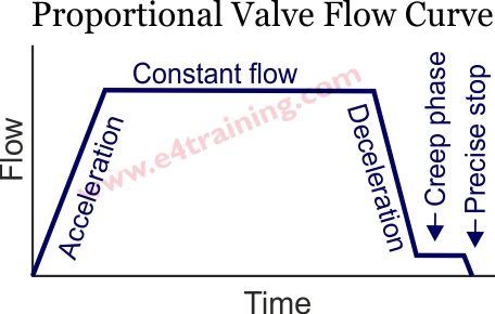
Our graph shows a typical operating cycle for a proportional valve when lifting and lowering a simple mass load.
A-B From points A to B we accelerate the load from stopped to the desired valve opening setting. The pressure drop across the valve remains relatively small Pv = P(supply) - P(load mass) - P(load acceleration).
B-C From point B to C the valve has reached 90% open and lifts the mass at constant speed Pv = P(supply) - P(load mass). The pressure drop across the valve increases as there is no force required to accelerate the load.
C We remain at point C while the valve remains at 90% and continues to lift the mass at constant speed Pv = P(supply) - P(load mass).
C-D We then start to decelerate the load to point C to point D. Initially the load inertia will try to maintain the same speed/flow until the valve pressure drop starts to brake it. Notice how the total Pv increases because the supply pressure an load inertia pressure are both working in the same directioin. Pv = P(supply) - P(load mass) + P(load deceleration). This phase should be a maximum of 25%.
D-A During the constant slowing phase point D to A, the valve is still braking the load so Pv remains high.
must control the supply pressure plus the load pressure meaning that for the same flow rate the valve only opens to say 40% of its full stroke.
Factors to consider
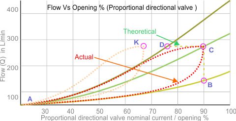
A. The valve pressure drop Pv is the total of both valve lands with the bore side seeing twice as much flow as the annulus side. Sometimes it is better to use a 2:1 spool, which will give similar pressure drops on the full flow, bore side as the half flow, annulus side.
B. If we only have Pv =10 bar then cylinder flow is just 100 L/min. If the cylinder load is then removed such that the valve pressure drop Pv becomes 90 bar, the flow will increase to 300 L/min. 100-300 L/min variation in flow/speed is probably unacceptable for an automatic machine cycle.
C. When comparing proportional valves always consider the flow rate at a specific pressure drop e.g. 100L/min at 90 bar Pv compared to 150 L/min at 90 bar Pv.
D. If a larger flow rated valve was used in an attempt to reduce the valve's pressure loss and therefore increase the pressure available to the load. Our curve shows that all that would happen is our Point C would move to Point K. The system will always balance with the same pressure drops because the load and supply pressures remain the same. All that has changed is the larger rated valve has opened slightly less and because the percentage control error at half stroke remains the same as it would be at full stroke. The control accuracy will always be worse with the larger valve.
E. Always maintain a minimum of 10 bar drop across a valve to avoid cavitation from falling loads.
F. Note how each Pv curve is not linear. The shape of the curve is determined by the shape of the control notch.
G. There are many more detail technical parameters that will have been considered at the design stage but have not been covered here. The component manufacturers will have specialist with specialist simulation software to identify and optimise the most appropriate valve for each application. These example should help you understand what is happening but you should always refer back to the machine designers before making any component changes.
Experiment to find out more
Experiment with load forces and how they affect valve pressure drops
Why use a pressure compensator
We should all now be very familiar with the fact that as the load changes the pressure drop across a valve will change. And as the pressure drop across the valve restriction changes the flow rate through the valve will change.
A pressure compensator will maintain a constant pressure drop across a valve and therefore a more constant flow rate through it. There will still be a tolerance to how accurately the flow is controlled but it should be significantly better than without one.
In mobile systems it is common for the pressure compensator setting to be fairly low e.g. 10-20 bar across the valve. This will help to keep the losses low to improve the vehicle's fuel consumption, although is likely to provide less accurate flow control. The different manufacturers also apply the pressure compensation valves in a number of different ways e.g some sensing before and some after the main spools (known as pre and post compensation). These variations are often due to manufacturer patents but they can have a significant effect on some of the performance characteristics.
In industrial system the compensators tend to be set between 20 - 30 bar although for good quality control it's likely that a pressure drop of 30% of the load pressure, will be used.
Factors to consider
A. A pressure compensator is likely to be fitted when load changes significantly during, or between, each cylinder cycle. Particularly if it goes over-centre e.g. from a positive to a negative load during one cylinder cycle.
B. Pressure compensators need to sense the load pressure while extending and retracting the cylinder. It's therefore common to see the a shuttle valve that senses back from the either the bore or annulus side of the cylinder, across the control valve, to the pressure compensating valve on the supply line to the valve.
C. Pressure compensators are available in meter-in or meter-out configurations (industrial), pre or post compensators (mobile).
D. Poorly specified meter-in compensators can loose control of the load while it is decelerating if the decelerating pressures are higher than the compensators spring setting.
E. Poorly specified meter-out compensators can lead to cylinder intensification. Counterbalance valves may also be required to ensure the loads are controlled safely.
F. Pressure compensators can lead to around a halving of the system stiffness and therefore greatly reduce the dynamic response capability.
Know your machine stiffness
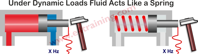
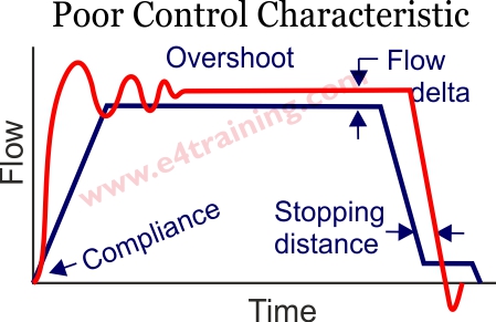
A machine's natural frequency is key to how it operates. Below 3-4Hz and it's likely the machine will bounce around uncontrollably but if you need high precision, high-speed control, then you will need something much stiffer.
In basic fluid power hydraulics we consider that hydraulic fluid is not compressible. But actually, it is and this should have been taken into account by the machine designer, if they have specified a proportional valve.
What is a machines natural frequency
If you support a heavy weight at the end of a long, thin, metal pole it will bounce up and down when you try to move it. The frequency at which it bounces up and down is known as its natural frequency of oscillation. Hold your hand closer towards the weight and the bouncing frequency will go up, an the amplitude down.
The same thing happens when you hit the load on a hydraulic cylinder with a hammer and measure the pressure ripples in the fluid. The frequency of the ripple will show you the natural frequency of the machine. Alternately you can get an approximate calculation of natural frequency from our cylinder and valve design guide here. Although this will not be appropriate for all systems.
Why is natural frequency so important
Let's consider our weight on the end of a metal pole again. If we move it very slowly it will not bounce. Accelerate or decelerate it more quickly and at some point, it will start to bounce. This point is known as the 'minimum acceleration time' and is calculated from the natural frequency. To stop our hydraulic systems from bouncing we must know what this value is and control our proportional valve's response time accordingly. The softer our system is then the slower we have to move it. If we need to control a machine very quickly then we will need to make sure that it is very stiff.
How do we control natural frequency
System natural frequency, or stiffness, is mostly determined by:
The reflected mass acting on the cylinder e.g. considering the square of any radius arm.
The stiffness of any mechanical load-carrying framework.
The area of the cylinder.
The length and diameter of the pipework between the valve's restricting lands and cylinder.
The length of only one pipe run if a pressure compensator is fitted.
From the above we can see that we need to increase the diameter of the cylinder or shorten the pipe lengths, to increase the system's natural frequency. Assuming we cannot change the machine or load.
Minimum acceleration time
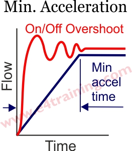 The minimum acceleration time is the quickest time you can accelerate a load to avoid any judder or harshness at the cylinder. A rule of thumb calculation for the minimum acceleration time can be made from the system natural frequency.

Of course, in practice, the minimum acceleration time might be limited by the valve's or the supply pressure response time.
Features required
The minimum acceleration time is controlled by how quickly the valves opens along with the shape of the spool notch. It's quite common to use a simple directional valve with a proportional spool, rather than a full proportional valve and accompanying electrical control. In this case the directional valve will include an orifice to control the rate at which the fluid leaves the end of the spool chamber and therefore the speed at which the valve opens.
Factors to consider
The valve opening and closing speed, including the flow rate across the valve as it opens and closes will vary depending on a wide range of factors including:
System load changes, fluid and coil temperatures, signal and valve variations, etc.
Experiment to find out more
Experiment with opening a simple proportional valve orifice.
Open loop control quality considerations
Proportional valves vary greatly in performance and price. Different applications will require different valves and there are likely to be range of different options for each application.
It is also possible that a higher quality valve will not work as well as a so called lower quality valve in certain applications. For example a valve with a fast reponse rate may actually go unstable in a system without the appropriate control or system dynamics.
Features available
The flow rate at a set pressure drop is always the first parameter to be considered.
Never exceed the power limit of a valve or the flow forces will take over the control.
Valves will be subject to a certain percentage error valve which can affect its performance at any opening percentage.
Differently levels of sensitivity and hysteres will affect the repeatability for how accurately the machine achieves its desired speed or positioning.
Force control and stroke controlled solenoids offer different control ranges and accuracies.
Factors to consider
Try to achieve a 30% valve pressure drop for good control.
Natural frequencies above 3-4 Hz, preferably 10-15 Hz or higher.
Experiment to find out more