Self-study lesson plans and training record download page.
Mobile control valve design strategy
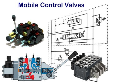
Designing hydraulic equipment for mobile machines requires building a lot of controls into a small box. Components must provide great performance as well as being lightweight, small, require minimum pipework and be leak free. From this, the mobile mono-block designs have evolved to combine all of the valves functions in one complete block. Industrial sandwich plates would be too big and the stack heights are unlikely to withstand the vibrations. The slice style design, as used on nearly all mobile equipment, provides an incredible amount of functionality within a very compact design. It also provides for simple installation with the minimum of pipework and leak points.
Our example circuits are shown with manual operating handles although these valves are commonly used with remote pilot valves or inbuilt electrical control.
The following sections describe some of the options and features that can be included.
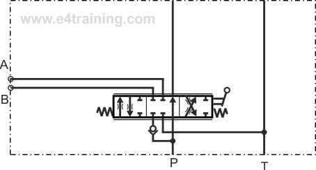
Basic mobile 6-way valve
The first thing to notice about the mobile valves is that they are 6 way rather than the standard industrial valve which is only 4 way. In fact, there is still only the supply, A and B cylinder lines and Return line external ports. The 5 and 6 connections in the spool are to feed the supply feed to pressure through the valve.
Most mobile valves have proportional control as indicated by the two lines on either side of the symbol. This allows them to provide manually controlled fluid flow rates and therefore actuator speed control.
There is also a check valve on the supply port to stop loaded cylinders simply back driving other actuators.
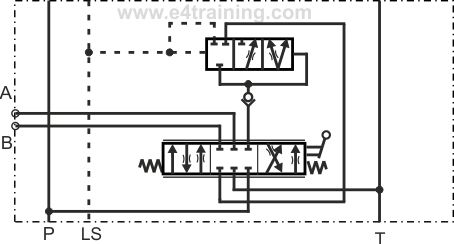
Open centre mobile valve designs
This example shows a closed and open centre valve, which means the main supply pressure passes straight through each valve section and onto the next section. When one section is operated it restricts the flow to the following spool slice. The means that each slice will have priority over the others but also that they don't all slow down if operated together.
Open centre valves are more popular in the US than in Europe, which prefers close centre designs.
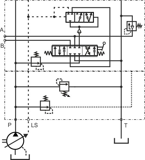
Closed centre mobile valve designs
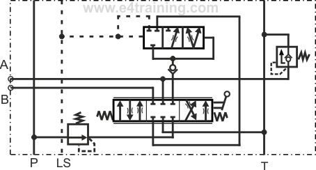
In this example, we show a closed centre valve design. The main inlet pressure supply is passed to ever spool slice via a direct flow path. The main spool supply port is closed when the valve is in its mid position so every valve section can draw the flow it requires when the lever is pushed. The supply flow then passes back into the main spool element where it's directed to either the A or B port. This may appear unnecessary at first but it's important for enabling the flow sharing and pressure compensation.
Pressure compensation
In the above diagram, we also show a pressure compensating valve above the spool. This pressure compensating valve is used to maintain a constant pressure drop across a proportional valve spool. When the spool is moved by a handle or solenoid valve, the orifice size it creates is proportional to the movement of the spool. However, the flow through the valve is dependent on the pressure drop across it so without a compensating valve there will be no reliable correlation between the position of the handle and the flow through the valve. By ensuring the spool always has the same pressure drop across it we can ensure that it will always give a similar flow rate depending on the position of the handle or electrical signal provided.
Pre and post-compensated valves
In the diagram above we show the pressure compensating valve located after the main spool. This is called a post-compensated valve. If the compensator valve was before spool it would be a pre-compensated valve. The difference is very important when it comes to flow sharing i.e. how consistently it shares the flow between each valve section. There are a number of patents covering how this is achieved and therefore a number of different techniques for achieving this. The Rexroth approach shown in our diagram is one of the more popular valves, with good flow sharing capabilities.
Load sensing signal
From the left side of the compensator valve, we see the feed for the load sensing system. The LS signal is fed back to the load sensing pump which is described in our pump controller section.
Essentially this signal is the actual load the actuator needs. It feeds back the required pressure for the supply to this valves so that the pump knows what pressure it needs to supply. A system of shuttle valves will always ensure that the highest pressure is sent back to the pump but if the LS signals are a long distance away from the pumps, as on large ships, for example, there may be an LS boost valves to compensate for the long line pressure drops and ensure the pump sees the full pressure it needs to send.
Reducing and relief valves
This example shows one mobile slice section with inbuilt reducing and relief valves.
The reducing valve sits before the main spool and will prevent the actuator providing too high a force to the load.
The relief valve will protect the actuator from high shock loads and also contains a non-return valve to protect the actuator from negative pressures that may be caused by the nature of the load acting on them.
Mono-block end plates
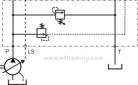
On the end of a stack of mono-block valves, there will be supply or tank return ports. These allow connections to the pump and reservoir but may also have other features such as safety relief valves or reducing valves to provide a constant pilot pressure to the proportional solenoid valves.