Self-study lesson plans and training record download page.
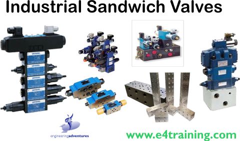
Industrial CETOP sandwich and manifold design strategies
This module discusses some common industrial design techniques including sandwich plate design, platen/manifold mounted design or cartridge design. We cover the history and reasons behind why these techniques have become so widely used along with discussing the types of application where they would be used.
Background to industrial hydraulic system design
Back in the late 1970s, there was a big issue throughout the industry with the amount of fluid that was being lost from hydraulic systems. This was not only a significant cost issue but also posed a major threat of injury due to slippage and fire, plus contamination of the environment.
A major research project was carried to identify the causes and find the best solutions. A brief summary of the conclusions is that everyone should reduce the number of leak points in the design as much as possible and only certain types of fittings should be used.
We will discuss fittings in another module but reducing the number of fittings meant moving from line-mounted valves towards manifold or cartridge designs.
Line mounted hydraulic valves
Most valves come with line-mounted body options so that they can be placed in the middle of a single length of pipe. This means a minimum of two adapters and two pipe fittings i.e. 4 additional leak points. Supporting the pipework and valve also becomes more complicated with any vibration adding to the risk of the fittings loosening and leaking.
Sandwich plate mounted valves
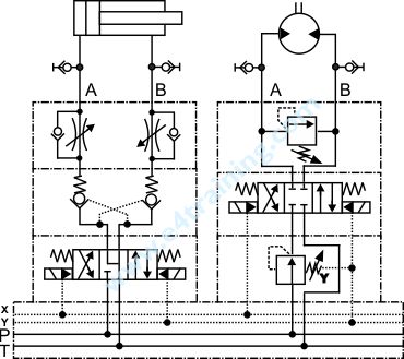
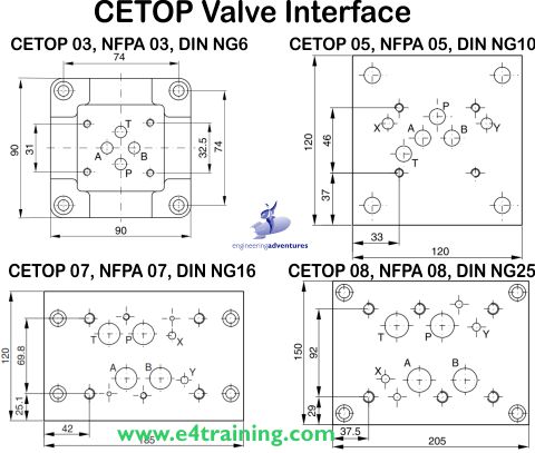
The hydraulics industry has universally adopted the CETOP interface for industrial design. This means we can buy standard strip manifolds to a line of hydraulic valves. We have a single supply and return port along with the cylinder supply A and B lines. Although we have seals between each slice, they are generally good quality, easily controlled connections and provide users stay within the recommended stack heights, they should not see unwanted leakage.
The designs for each individual cylinder are constructed by adding slices underneath each valve. Most valve manufacturers produce the full range of the standard valves that are required to control most actuator application possibilities. There will always be uniquely custom designs however these can often be added as custom slices where the slice manifold is unique, the uses standard cartridge valves inside.
One of the major benefits of sandwich plate design is the ability to modify the circuits during commissioning. Equipment lead times can be very short and its common for designs to change as the work progresses. There can often be mistakes or missing information that only gets discovered during commissioning but still needs to be corrected. With sandwich plate designs it's easy for someone to swap out one slice or add another. In fact some companies deliberately over order the number of valve stations on each manifold, just in case they need to add another actuator later.
Manifold or platen mounted designs
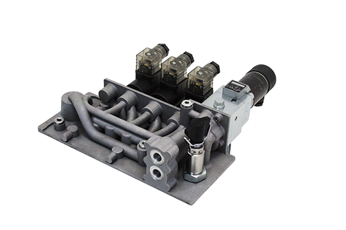
If circuits are too complex to allow them to be realised using sandwich plate designs, then custom manifolds must be used. Here we have complete freedom to make the circuits we require. Each valve can be mounted directly onto the manifold without the need to stack valves too highly. All connections are made inside the manifold, eliminating the need for any external pipework.
Custom manifolds are sometimes a preferable method of manufacture with production machines although they can grow quite large when complex circuits are required. It might be worth checking their weight or making a mock-up to get a good idea of how big it will be or considering a 3D printed manifold.
Always be careful to check you have full drill depths and flow paths plus all bores are clean and free of burrs.