Hydraulic pump and motor symbols
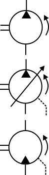
The top symbol shows a fixed displacement hydraulic pump that rotates in an anticlockwise direction (shown by the arrow) when viewed onto the drive flange and drive-shaft. The black triangle shows it is a hydraulic pump and which direction the flow will go in.
If the triangle was clear it would indicate a pneumatic pump, or compressor, rather than a hydraulic pump.
If the symbol was reversed, as shown in the bottom image, it shows a motor rather than a pump.
The middle symbol has an arrow through it indicating a variable displacement pump. It also shows a case drain line coming from the side of the pump casing. Generally, it is only fixed displacement pumps that can work without a case drain line.
Bi-directional pumps and motors
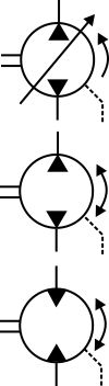
Bi-directional pumps and motors can provide flow or rotate in both directions.
The top symbol shows a variable displacement, bi-directional pump. It only rotates in a counter-clockwise rotation, but can provide flow in either direction depending on the variable displacement setting.
The middle symbol shows a fixed displacement pump that can provide flow in both directions because it can rotate in both directions.
The bottom symbols shows a fixed displacement, bi-directional motor, which can rotate in both directions.
Intensifiers and combined pump/motors
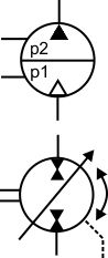
The top symbol shows an air/fluid intensifier because the bottom triangle is a pneumatic motor and the top triangle a hydraulic pump. There is no driveshaft. Air at P1 creates fluid pressure at P2.
The bottom symbol shows a combined pump and motor that has a variable displacement and can rotate in either direction.
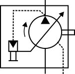
Simplified pump control symbols
Variable displacement pumps are commonly drawn with detailed circuits showing how their internal control systems function. There are also standard, simplified, ISO symbols for the different types of control and we have provided two examples here.
The top symbol is a variable displacement pump that rotates in a clockwise direction. It has an electro-hydraulic control of its displacement and a case drain line.
The bottom symbol shows another variable displacement pump with both pressure and flow control of its displacement. The flow control is achieved by sensing the pressure drop across an external, variable orifice. External pressure control valves can also be used to remotely control pressure setting levels.
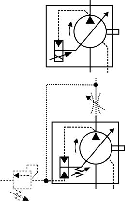
Detailed pump control symbols
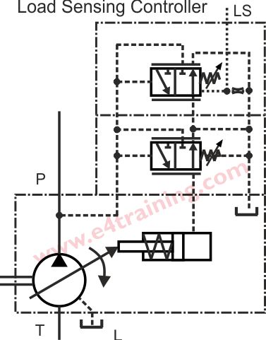
This example shows how the standard control valve symbols can be used to provide more detailed information on how a pump is controlled. Our pump training module includes details on how the different pump controllers perform.
Describe the pump shown here
 Can you describe the type of pump that is shown in this symbol.