Read in conjunction with simulation experiments
Self-study lesson plans and training record download page.
Hydraulic pump and motor circuit operation
This module will discuss a typical pump/motor circuit and demonstrates how pressure and flow can be controlled in the system. It also demonstrates the typical power loss using fixed pumps and flow control valves which can generate heat in a system. It also shows how this can be eliminated using a pressure compensated pump.
Open centre directional control valve
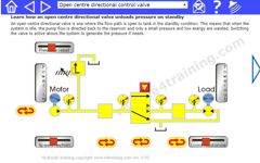
Go to the experiment section and select 'Open centre directional control valve' from the drop down menu. The directional valve is set with supply flow to tank. The fixed displacement pump is creating flow but it is directed straight to the reservoir so the load does not create any pressure and losses and power input are low.
Closed centre directional control valve
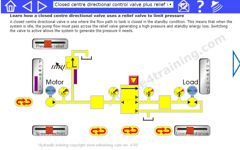
With the directional valve supplying the flow to the motor inlet, the motor will rotate. The supply pressure will be the same as the load pressure. Changing the load pressure changes the supply pressure.
Fixed displacement pump with relief valve
Increasing the load pressure above the supply pressure and the motor will stop as the relief valve opens. Increasing and decreasing the relief valve setting above and below the motor load setting will start and stop the motor respectively.
Pressure reducing valve
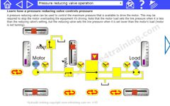
When we add a reducing valve to the virtual test rig circuit we limit the pressure downstream of the valve. As the reducing valve is adjusted the downstream pressure will increase until it reaches the motor load pressure and the motor starts to turn. When the reducing valve's set pressure is below the load pressure the motor will not start.
In this application the relief valve approach would use less energy so is probably preferable. However, there is no correct way to control pressure as this depends on each individual application. Reducing valves can be more efficient and can often provide more stable control. The decision should be based on looking at the power consumption, as we see in our example simulation, and also studying the valve design detail, as outlined in our previous training module, to evaluate the level of pilot leakage and quality of control lands.
More details on pilot systems and quality of control are provided in our strategies module.
Flow control valves

With a flow control valve, in this case, an adjustable orifice, in front of the motor we should be able to control its speed. The load pressure is set by the motor load but the supply pressure will equal the load pressure plus the pressure drop across the orifice. Depending on the type of supply we have.
When we use a fixed displacement pump, whatever setting we have on the flow control valve, the motor speed will be equivalent to that of the pump flow rates. Only the supply pressure will increase as the pressure drop across the orifice increases.
Once the supply pressure reaches the relief valve setting then the relief valve will open and release some flow. Now we only have a fixed pressure drop across our orifice so as we change the orifice size, the flow through the orifice will and the motor will speed up or slow down accordingly.
The above will also happen when using a variable displacement, pressure compensated pump although this time the pump displacement reduces to reduce the input power required.
With a load sensing pump, the speed could stay constant as long as the supply pressure can increase or decrease to match the motor load pressure. Under these conditions, the flow and pressure drop across the orifice would remain the same.
If the supply pressure is changed and the motor load remains constant then the pressure drop across the orifice must change and therefore the flow rate and motor speed must change too.
If the supply pressure or relief valve are controlling the pressure and therefore remain constant, as we change the motor load the motor speed will change as well because the pressure drop across the orifice will change and this will affect the flow across the orifice.
Pressure compensated flow control valve
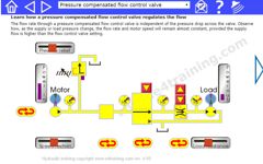
With a pressure compensated flow control valve, the flow remains constant no matter what the supply or load pressures are. Pressure compensated valves typically have a fixed pressure drop of between 10 and 20 bar. Unfortunately, that rarely means the supply pressure will equal the load pressure plus say 15 bar.
A fixed displacement pump will always supply the same flow if its speed is constant, therefore if the pressure compensated valve is set to need less flow, the excess flow must go someone and will therefore instantly increase to the maximum setting of the relief valve and open that to release the excess flow.
If a variable displacement, pressure compensated pump is used, then the pump will instantly adjust to provide the correct flow but also increase the pressure to its maximum pressure setting, irrespective of the motor load setting.
In both pump cases, the overall system efficiency is likely to be different depending on the speeds and pressures etc. Each application should be looked at separately as it may be that using a pressure compensated flow control valve will be less efficient than using a fixed orifice, but having a flow rate that is dependent of load pressure is unacceptable.
Experiment with new circuit layouts
Use our simulation to examine how valves affect the input and output power consumption of a simple hydraulic pumps and motor circuit. We look at different ways of controlling the motor loads and see the effects on power consumption. We show you how to experiment with our circuit simulations to explore its function and better understand how the relationship between power, load, flow and pressure work.