Self-study lesson plans and training record download page.
Tips for operating and maintaining

Hydraulic filters are generally specified at normal operating temperatures rather than the lower, cold-start or winter running temperatures. It's quite common for filters to exceed their design pressure differentials at start-up and if electrical signals are provided, these may include modifications to software routines to stop the failure alarms. Start-up readings can provide a clearer indication of when filter elements will require changing.
While system designers will try to predict in-service contamination levels they may never know the exact air quality, duty cycle or environmental conditions the equipment will work in. These may also change throughout the year as conditions get dustier or units travel to different locations. It's therefore vital that maintenance engineers regularly check the fluid contamination levels and take the relevant actions when necessary. If contamination levels do rise it may not be necessary to increase the size of the filters. Passing additional fluid through the existing filters will help to clean the system. It may be that bypass flows can be run through the system filters while the equipment is not operating, or if not, then external filter packs left to run for longer periods to thoroughly clean the fluid in the reservoirs.
Design features and operating characteristics
Of vital importance with every hydraulic system is:
1. Knowing the key aspects of the design that will be sensitive to contamination.
2. Applying effective techniques capable of protecting all of the sensitive areas.
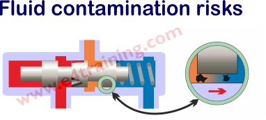
Point 1 means understanding where the dirt is coming from. Perhaps dust in the air is coming into contact with fluid in the reservoir or when cylinder rods retract they bring dirt in with them. Do any actuators work in particularly dirty environments and have areas that contact both the fluid and air? Do any valves have control shafts or mechanical actuators with surfaces that contact both air and fluid? Do any components have contacting surfaces? Fluid power components should always have thin film hydrostatic lubrication to stop surfaces touching because as soon as any metal components come into contact, they will start wearing and create tiny metal particles that will block other valves. Gear pumps, vane pumps and sideloaded actuators can all generate debris under normal working conditions and must be avoided if you require the cleanest of systems.
Point 2 essentially means using filters in the correct locations to stop the debris from moving into the valves. Pressure filters protect the circuit from the pumps and return line filters protect everything from dirt that enters via the actuators. Offline filters provide additional cleaning if the dirt entering the fluid is higher or similar to the dirt being removed by the inline filters.
It may not always be possible to predict at the design stage, the exact balance between the quantity of dirt entering, or being generated by the system, and that being removed by the filters. For this reason it's normal to monitor the in-service contamination levels and modify the level of filtration, if required.
Common sources of contamination:
New fluid is dirty and needs to be flushed clean during and after filling.
Manufactured parts, handling, delivery & installation will all add contamination.
The surrounding air is dirty and will enter the fluid via air breathers, cylinder rods, maintenance work etc.
All metal parts that touch will wear and create contaminants.
Typical spool clearance and particle sizes:
Spool clearance 6-10 micron.
(Human hair = 70micron, grain of salt = 100micron, limit of visibility = 40micron, red blood cell = 8micron)
Typical air quality:
Urban regions 3-7 mg/m3
General mechanical engineering 9-23 mg/m3
Construction industry (wheeled vehicles) 8-35 mg/m3
Construction industry (tracked vehicles) 35-100 mg/m3
Heavy industry 50-70 mg/m3
How to specify hydraulic filters
Hydraulic designers and maintenance engineering must understand exactly which are the most sensitive parts of their systems and where the dirt could come from.The level of filtration required will likely be understood from previous systems or similar designs. If not then there is an industry guideline document from the Department of Trade and Industry (P5) called, Guidelines to contamination control in hydraulic fluid power systems. This provides an approach to predicting filter ratings and has been reproduced by Parker here . Use this if you have no previous experience or are suffering from reliability issues.
Select the number and type of filters based on where your dirt will enter the system and where you have sufficient flow to allow the filters to clean effectively. If the working flow is not sufficient then consider how an additional flushing flow can be included within the design.
Select the filter element material type based on the fluid you will be using. Different fluids require different elements; as can some of the environmental disposal legislation.
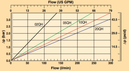
Select the filter based on the manufacturer's pressure drop curves against your maximum rated flow. They should have curves for the housing as well as the filter element. Both will be affected by the fluid type and viscosity although the element is likely to be more significant and should be covered by a specific gradient coefficient in the manufacturer's datasheet. Use the manufacturers recommended calculation to size the correct filter for your maximum flow rate. You should design for as low a pressure drop as possible but always allowing for an increase in pressure as the filter clogs, and before the bypass check limit is reached. Cold start conditions may also require a larger filter size to reduce filter pressure drops.
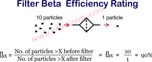
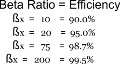
The filter will probably be selected by its absolute rating e.g. 3, 5, or 10micron. However, beta rating is a much better measure of its likely performance. This is defined by a standardised multi-pass test (ISO 16889:1999) and all filters should be specified to Beta(x)>200 for effective performance.
Air breather sizing guidelines
 Air filter element ratings must be equal to or smaller than hydraulic filter element rating.
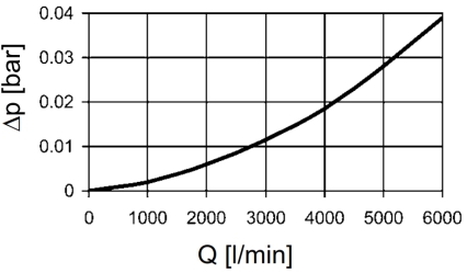
Maximum initial pressure loss when clean, at calculated flow, must not exceed 0.01 bar
Calculated air flow rate = Max flow rate of the pump or displaced volumes x operating condition factor.
Typically operating condition factors are:
F= 1-2 for low dust environments.
F= 3 -6 average dust environment and intermittent monitoring.
F= 7-10 high dust environment with minimal monitoring.
Example air breather sizing calculation
For this application, we have selected an operating condition flow factor F of 5 as we will have relatively low usage and the condition will be check regularly.
The maximum flow from cylinder return is 300L/min
Calculated air flow rate = 300 * 5 = 1500 L/min
Design Tips, techniques and potential issues
Consider how maintenance engineers will gain access to change the filters. Some filter bowls need the full height of the filter as clearance to change the element. Always check the datasheet for space requirements.
Consider the potential for flow peaks that might damage the filter membrane. Pressure filters should not be mounted after accumulators and return filters must be sized appropriately to absorb any flow shocks, particularly at low temperatures.
Pressure filters will require differential pressure indicators as, unlike most return line filters, they have no tank reference feeds.
Steel spin on elements are sometimes used if there is a fire risk.